Is it possible to use a transistor to connect the emitter to the collector. For beginners - transistors
Transistors are at the heart of most electronic devices. It can be in the form of separate radio components, or as part of microcircuits. Even the most complex microprocessor consists of a great many tiny transistors packed tightly into its mighty crystal.
Transistors are different. The two main groups are bipolar and field. The bipolar transistor is indicated on the diagram, as shown in Figure 1. It can be direct (p-p-p) and reverse (p-p-p) conductivity. The structure of the transistor, and the physical processes occurring in it, are studied at school, so we will not talk about it here - so to speak, closer to practice. In essence, the difference is that p-p-p transistors connected so that their emitter receives a positive voltage potential, and the collector receives a negative one. For transistors n-p -p - everything is vice versa, a negative potential is given to the emitter, positive to the collector.
Why do you need a transistor? It is mainly used to amplify current, signals, voltage. And amplification occurs due to the power supply. I will try to explain the principle of work "on the fingers". The car has a vacuum brake booster. When the driver presses the brake pedal, his membrane moves and a valve opens through which the car's engine sucks in this membrane, adding force to it. As a result, a weak force on the brake pedal leads to a strong force on the brake pads. And the addition of force occurs due to the power of the running motor of the machine.

It's the same with the transistor. A weak current is applied to the base (Fig. 2). Under the influence of this current, the conductivity of the collector - emitter increases and a much stronger current flows from the power source through the collector. The weak base current changes, and the strong collector current changes accordingly. Ideally, the collector current graph looks like an enlarged copy of the base current graph.
This difference between a weak base current and a strong collector current is called the current gain of the transistor, and is denoted by I21e. It is defined as follows: h21e = Ik /I6 (collector current divided by base current). The more given parameter, the better the amplifying properties of the transistor.
But this is all ideal. In fact, the dependence of the collector current on the base voltage is not so linear. Should be remembered BAX diode, where at the very bottom of the current characteristic is very small, and begins to rise sharply when the voltage reaches a certain value. Since the transistor is based on the same physical processes, there is a similar “defect” here.

If we assemble the amplifier circuit shown in Figure 3 and speak into the microphone, there will be no sound in the speaker. Because the voltage at the microphone is very low, it is below the threshold for opening the transistor. Here, not only will there be no amplification, but on the contrary, there will be signal attenuation.

In order for the transistor to work as an amplifier, you need to increase the voltage at its base. This can be done somehow by increasing the voltage at the output of the microphone. But then the meaning of the amplifier is lost. Or you need to cheat, and apply some constant voltage to the base of the transistor (Fig. 4) through a resistor, such that the transistor opens slightly. And apply a weak alternating voltage to the base of this transistor through a capacitor. Now the most important thing is that a weak alternating voltage will add up with a constant voltage at the base. The voltage at the base will change in time with a weak alternating voltage. But since the DC voltage has shifted the operating point of the transistor to a steep linear section of the characteristic, amplification occurs.
Simply put, a weak voltage did not have the strength to open the transistor, and we added a constant voltage to help him, which slightly opened the transistor. Even easier (again with water), for example, there is a tightly screwed screw, and the child cannot turn it. But dad can open this propeller by turning it to a slightly open position, in which it rotates easily. Now the child can regulate the water pressure within certain limits. Here, the baby is a weak AC voltage, and dad is a DC voltage applied to the base of the transistor through a resistor.
The constant voltage that is applied to the base of a transistor to shift its mode of operation to a region with a steeper and more linear characteristic is called the bias voltage. By changing this voltage, we can even adjust the gain of the amplifier stage.
But transistors are not always used with a bias voltage. For example, in the amplifying stages of transmitters, the bias voltage may not be applied to the bases of transistors, since the amplitude of the input alternating voltage there is quite enough to “build up” the transistor.
And if the transistor is used not as an amplifier, but as a key, then the bias voltage is also not given to the base. Simply, when the key must be closed, the voltage at the base is zero, and when it must be open, voltage is applied to the base sufficient to open the transistor. This is usually used in digital electronics, where there are only zeros (no voltage) and ones (voltage) and no intermediate values.

Figure 5 shows a practical diagram of how to make radio dots from a loudspeaker computer column. You need a simple single-program speaker with only one plug for connecting to the radio network (multi-program has a second plug for the mains). There is no need to make any changes to the speaker circuit. It is connected to the collector of the transistor in the same way as to the radio network.
Inside the single-program loudspeaker there is a speaker, a variable resistor for volume control and a transformer. All this is needed, and it remains. When you open the case of the loudspeaker, solder the collector of the transistor and the plus of the power source to the places to which its wire with the plug is soldered. The wire itself can be removed.
To connect to a computer, you need a shielded wire with an appropriate plug at the end. Or a regular two-wire wire. If the wire is shielded, connect the braid to the emitter of the transistor, and the central core to the capacitor C1.
The signal from the computer sound card is fed through the plug to the capacitor C1. The supply voltage is supplied from the mains power supply. The power supply from the game console to the TV is best suited, such as "Dandy", "Kanga". In general, any power supply with an output voltage of 7V to 12V . To connect to the power supply, you need an appropriate socket; you need to install it on the loudspeaker case by drilling a hole for it. Although, of course, you can solder the wires from the power supply and directly to the circuit. When connecting the power supply, the polarity must be observed. Diode VD 1 in principle, it is not needed, but it protects the circuit from failure if you confuse the plus and minus of the power supply. Without it, if the power is connected incorrectly, the transistor can be burned, and with a diode, if you confuse the poles of the power supply, the circuit will simply not turn on.
KT315 transistor in a rectangular case, which has a bevel on one side (shown in the figure). Now, if you turn it away from you with this bevel, and with the leads up, then the base will be on the left, the emitter on the right, and the collector in the middle. Suitable transistor KT315 with any letter (KT315A, KT315B ...). The transistor must be soldered correctly, without confusing its conclusions. If you make a mistake and turn on the power, he can die. Therefore, after you solder everything, do not be too lazy three times to check the correctness of the installation, whether the terminals of the transistor, capacitors, and diode are correctly soldered. And only when you are 100% sure, turn it on.
Diode VD 1 type KD209. It has an anode on it. You can put another diode, for example, 1N4004 or some other. If the diode is soldered incorrectly, the circuit will work
will not be. So, if everything is turned on, but does not work, start by checking the correct connection of the diode.
A few more reasons that the scheme may not work:
Power supply connected incorrectly.
There is no signal at the output of the computer, or the volume is reduced or turned off by adjustments in the computer program.
Speaker volume control in minimum position.
Capacitors - electrolytic, voltage not less 12V Our K50-16, K50-35 or imported analogues will do. It should be noted that our capacitors have a plus sign on the case near the positive terminal, while imported capacitors have a minus sign or a wide vertical strip at the negative terminal. Instead of a 10 microfarad capacitor, you can choose any capacitance from 2 microfarads to 20 microfarads. Instead of a 100 uF capacitor, a capacitor of any capacitance of at least 100 uF will do.
The figure below the diagram shows the wiring diagram, on which the soldering points are marked with dots. Do not confuse solder joints with wire crossings. The installation is made by a hinged method, using the conclusions of parts and wiring. It is desirable to place the entire circuit inside the loudspeaker case (there is usually a lot of space there).

If everything works, but it emits a lot of noise, it means that you mixed up the wires going to sound card. Swap them.
DO NOT power the circuit from a computer power supply!
For the stereo version, you can make two speakers by combining the inputs into one stereo cable for connecting to a sound card, and power both speakers from one power supply.
Of course, with one transistor stage, the speaker will not sound loud, but enough for listening in a small room. The volume can be adjusted both with the computer regulator and with the knob that the loudspeaker has.
Andreev S.
Good day dear radio amateurs!
I welcome you to the site ""
In this lesson Beginner radio schools we will continue to study semiconductors. In the last lesson, we looked at diodes, and in this lesson we will consider a more complex semiconductor element - transistors.
Transistor is a more complex semiconductor structure than diode. It consists of three layers of silicon (there are also germanium transistors) with different conductivity. These can be n-p-n or p-n-p structures. The functioning of transistors, as well as diodes, is based on the properties of p-n junctions.
The central or middle layer is called base(B), and the other two, respectively, emitter(E) and collector(TO). It should be noted that there is no significant difference between the two types of transistors, and many circuits can be assembled with one type or another, as long as the correct polarity of the power supply is observed. The figure below shows a schematic diagram of transistors, the p-n-p transistor is different from the transistor n-p-n direction emitter arrows:
 There are two main types of transistors: bipolar And unipolar, which differ in design features. Within each type there are many varieties. The main difference between these two types of transistors is that the control of the processes occurring during the operation of the device in the bipolar transistor is carried out by the input current, and in the unipolar transistor - by the input voltage.
Bipolar transistors, as mentioned above, are a layer cake of three layers. In a simplified form, a transistor can be represented as two back-to-back diodes:
 (at the same time, it should be noted that the base-emitter junction is a conventional zener diode, the stabilization voltage of which is 7 ... 10 volts). The health of the transistor can be checked in the same way as the health of the diode, with a conventional ohmmeter, measuring the resistance between its terminals. Transitions similar to those found in a diode exist in a transistor between base and collector, and between base and emitter. In practice, this method for testing transistors is used very often. If an ohmmeter is connected between the collector and emitter terminals, the device will show an open circuit (with a working transistor), which is natural since the diodes are connected in opposite directions. And this means that for any polarity of the applied voltage, one of the diodes is turned on in the forward direction, and the second in the opposite direction, so no current will flow.
Combining two pairs of transitions leads to the manifestation of an extremely interesting property, called transistor effect. If a voltage is applied to the transistor between the collector and the emitter, there will be practically no current (which was discussed a little higher). If, however, the connection is made in accordance with the diagram (as in the figure below), where voltage is applied to the base through the limiting resistance (so as not to damage the transistor), then a current stronger than the base current will flow through the collector. As the base current increases, the collector current will also increase.
 By using measuring device you can determine the ratio of base, collector and emitter currents. This can be checked in a simple way. If you keep the supply voltage, for example, at the level of 4.5 V, changing the resistance value in the base circuit from R to R / 2, the base current will double, and the collector current will increase proportionally, for example:
Therefore, for any voltage across resistance R, the collector current will be 99 times the base current, that is, the transistor has a current gain equal to 99. In other words, the transistor amplifies the base current by 99 times. This coefficient is denoted by the letter ? . The gain is equal to the ratio of the collector current to the base current:
? = Ik / Ib
An alternating voltage can also be applied to the base of the transistor. But, it is necessary that the transistor work in linear mode. For normal operation in linear mode, the transistor must apply a DC bias voltage to the base and supply an AC voltage, which it will amplify. Thus, transistors amplify weak voltages coming from a microphone, for example, to a level that can drive a loudspeaker. If the gain is not sufficient, several transistors or their series stages can be used. In order not to violate the operating modes of each of them in direct current (at which linearity is ensured) when connecting the cascades, isolation capacitors are used. Bipolar transistors have electrical characteristics that provide them with certain advantages over other amplifying components.
As we already know, there are also (except bipolar) and unipolar transistors. Let's briefly look at two of them - field And unijunction transistors. Like bipolar, they are of two types and have three outputs:
 The electrodes of field-effect transistors are: gate– Z, stock- C, corresponding to the collector and source– And, identified with the emitter. FETs with n- and p-channel differ in the direction of the gate arrow. Unijunction transistors, sometimes referred to as double-base diodes, are mainly used in pulsed periodic signal generator circuits.
There are three fundamental circuits for switching on transistors in an amplifier stage:
? common emitter(A)
? with common manifold(b)
? with common base(V)
 Common emitter bipolar transistor, depending on the output impedance of the power supply R1 and the load resistance Rl amplifies the input signal both in voltage and current. The gain of a bipolar transistor is denoted as h21e(it reads: ash-two-one-e, where e is a circuit with a common emitter), and it is different for each transistor. The value of the coefficient h21e (its full name is static base current transfer coefficient h21e) depends only on the thickness of the base of the transistor (it cannot be changed) and on the voltage between the collector and emitter, therefore, at a low voltage (less than 20 V), its current transfer coefficient at any collector current is practically unchanged and slightly increases with increasing collector voltage.
current gain – Kus.i And voltage gain – Kus.u of a bipolar transistor connected according to a common emitter circuit depends on the ratio of the load resistance (indicated as Rn in the diagram) and the signal source (indicated as R1 in the diagram). If the resistance of the signal source in h21e times less than the load resistance, then the voltage gain is slightly less than unity (0.95 ... 0.99), and the current gain is h21e. When the signal source impedance is more than h21e times less than the load resistance, then the current gain remains unchanged (equal to h21e), and the voltage gain decreases. If, on the contrary, the input resistance is reduced, then the voltage gain becomes greater than unity, and the current gain, while limiting the current flowing through the base-emitter junction of the transistor, does not change. The common emitter circuit is the only bipolar transistor circuit that requires input (drive) current limiting. Several conclusions can be drawn:- the base current of the transistor must be limited, otherwise either the transistor or the circuit controlling it will burn out; - with the help of a transistor connected according to the OE circuit, it is very easy to control a high-voltage load with a low-voltage signal source. A significant current flows through the base, and hence the collector junctions at a base-emitter voltage of only 0.8 ... 1.5 V. If the amplitude (voltage) is greater than this value, you need to put a current-limiting resistor (R1) between the base of the transistor and the output of the control circuit. You can calculate its resistance using the formulas:
Ir1=Irn/h21e R1=Ucontrol/Ir1 Where:
Irн– current through the load, A; Upr– signal source voltage, V; R1 is the resistance of the resistor, Ohm.
Another feature of the OE circuit is that the voltage drop across the collector-emitter junction of the transistor can be practically reduced to zero. But for this it is necessary to significantly increase the base current, which is not very profitable. Therefore, this mode of operation of transistors is used only in pulsed, digital circuits.
Transistor, operating in an amplifier circuit analog signal , should provide approximately the same amplification of signals with different amplitudes relative to some “average” voltage. To do this, you need to “open” it a little, trying not to “overdo it”. As you can see from the picture below (left):
 the collector current and the voltage drop across the transistor with a smooth increase in the base current initially change almost linearly, and only then, with the onset saturation transistor, are pressed against the axes of the graph. We are only interested in the straight parts of the lines (before saturation) - it is obvious that they symbolize the linear amplification of the signal, that is, if the control current changes several times, the collector current (load voltage) will change by the same amount.
The analog waveform is shown in the figure above (right). As can be seen from the graph, the signal amplitude constantly pulsates relative to a certain average voltage Uav, and it can either increase or decrease. But the bipolar transistor reacts only to an increase in input voltage (or rather current). Conclusion: you need to make sure that the transistor, even with the minimum amplitude of the input signal, is slightly ajar. With an average amplitude Uav, it will open a little stronger, and with a maximum Umax, it will open as much as possible. But at the same time, it should not enter saturation mode (see figure above) - in this mode, the output current ceases to depend linearly on the input, as a result of which a strong signal distortion occurs.
Let's turn again to the form of an analog signal. Since both the maximum and minimum amplitudes of the input signal relative to the average are approximately the same in magnitude (and opposite in sign), we need to apply such a direct current to the base of the transistor (bias current - Icm) so that at the “average” voltage at the input the transistor is exactly half open. Then, with a decrease in the input current, the transistor will close and the collector current will decrease, and with an increase in the input current, it will open even more.
In all experiments, transistors KT315B, diodes D9B, miniature incandescent lamps 2.5V x 0.068A are used. Headphones - high-resistance type TON-2. Variable capacitor - any, with a capacity of 15 ... 180 pF. The power supply battery consists of two 4.5V 3R12 batteries connected in series. The lamps can be replaced with series-connected LED type AL307A and a resistor with a nominal value of 1 kOhm.
EXPERIMENT 1
ELECTRICAL DIAGRAM (conductors, semiconductors and insulators)
Electric current is the directed movement of electrons from one pole to another under the influence of voltage (9 V battery).
All electrons have the same negative charge. Atoms of different substances have different numbers of electrons. Most electrons are firmly bound to atoms, but there are also so-called "free", or valence, electrons. If a voltage is applied to the ends of the conductor, then free electrons will begin to move towards the positive pole of the battery.
In some materials, the movement of electrons is relatively free, they are called conductors; in others, movement is difficult, they are called semiconductors; thirdly, it is generally impossible; such materials are called insulators, or dielectrics.
Metals are good current conductors. Substances such as mica, porcelain, glass, silk, paper, cotton are insulators.
Semiconductors include germanium, silicon, etc. These substances become conductors under certain conditions. This property is used in the production of semiconductor devices - diodes, transistors.

Rice. 1. Determination of water conductivity
This experiment demonstrates the operation of a simple electrical circuit and the difference in conductance between conductors, semiconductors, and dielectrics.
Assemble the circuit as shown in Fig. 1, and bring the bare ends of the wires to the front of the board. Connect the bare ends together, the bulb will light up. This means that through the circuit passes electricity.
With two wires, you can test the conductivity of various materials. To accurately determine the conductivity of certain materials, special instruments are needed. (By the brightness of the lamp, one can only determine whether the material under study is a good or bad conductor.)
Attach the bare ends of the two conductors to a piece of dry wood at a short distance from each other. The light bulb will not light. This means that dry wood is a dielectric. If the bare ends of two conductors are attached to aluminum, copper or steel, the light bulb will burn. This suggests that metals are good conductors of electric current.
Dip the bare ends of the conductors into a glass of tap water (Fig. 1, a). The lamp does not light. This means that water is a poor conductor of current. If you add a little salt to the water and repeat the experiment (Fig. 1, b), the bulb will light up, which indicates the flow of current in the circuit.
The 56 ohm resistor in this circuit and in all subsequent experiments serves to limit the current in the circuit.
EXPERIMENT 2
DIODE ACTION
The purpose of this experiment is to demonstrate that a diode conducts well in one direction and does not conduct in the opposite direction.
Assemble the circuit as shown in Fig. 2, a. The lamp will be on. Rotate the diode by 180° (Fig. 2, b). The light bulb will not light.
And now let's try to understand the physical essence of the experiment.

Rice. 2. The action of a semiconductor diode in an electronic circuit.
The semiconductor substances germanium and silicon each have four free, or valence, electrons. Semiconductor atoms bind into dense crystals (crystal lattice) (Fig. 3, a).

Rice. 3. Crystal lattice of semiconductors.
If an impurity is introduced into a semiconductor having four valence electrons, for example, arsenic, which has five valence electrons (Fig. 3, b), then the fifth electron in the crystal will be free. Such impurities provide electronic conductivity, or n-type conductivity.
Impurities having a lower valency than semiconductor atoms have the ability to attach electrons to themselves; such impurities provide hole or p-type conductivity (Fig. 3c).

Rice. 4. pn junctions in a semiconductor diode.
A semiconductor diode consists of a junction of p- and n-type materials (p-n-junction) (Fig. 4, a). Depending on the polarity of the applied voltage, the p-n junction can either promote (Fig. 4, d) or prevent (Fig. 4, c) the passage of electric current. At the boundary of two semiconductors, even before the application of an external voltage, a binary electric layer is created with a local electric field of strength E 0 (Fig. 4, b).
If an alternating current is passed through the diode, then the diode will pass only the positive half-wave (Fig. 4d), and the negative will not pass (see Fig. 4, c). The diode thus converts or "rectifies" the AC to DC.
EXPERIMENT 3
HOW A TRANSISTOR WORKS
This experiment clearly demonstrates the main function of the transistor, which is a current amplifier. A small drive current in the base circuit can cause a large current in the emitter-collector circuit. By changing the resistance of the base resistor, you can change the collector current.

Assemble the circuit (Fig. 5). Put resistors into the circuit in turn: 1 MΩ, 470 kΩ, 100 kΩ, 22 kΩ, 10 kΩ. You may notice that with 1 MΩ and 470 kΩ resistors, the light does not light; 100 kOhm - the light bulb barely burns; 22 kOhm - the light bulb burns brighter; full brightness is observed when a 10 kΩ base resistor is connected.
|
Rice. 6. Transistor with n-p-n structure. |
Rice. 7. Transistor with p-n-p structure. |


A transistor is essentially two semiconductor diodes that have one common area - the base. If, in this case, the region with p-conductivity turns out to be common, then a transistor with an n-p-n structure will be obtained (Fig. 6); if the common area is with n-conductivity, then the transistor will be with the p-n-p structure (Fig. 7).
The area of the transistor that emits (emigrates) current carriers is called the emitter; the area that collects current carriers is called the collector. The zone enclosed between these areas is called the base. The transition between the emitter and the base is called the emitter, and between the base and the collector - the collector.
On fig. 5 shows the inclusion of an n-p-n type transistor in an electrical circuit.
When connected to a transistor circuit pnp type the polarity of the battery B is reversed.
For currents flowing through a transistor, there is a dependence
I e \u003d I b + I to
Transistors are characterized by a current gain, denoted by the letter β, which is the ratio of the increase in collector current to the change in base current.
The value of β ranges from several tens to several hundreds of units, depending on the type of transistor.
EXPERIMENT 4
PROPERTIES OF THE CAPACITOR
By studying the principle of operation of a transistor, you can demonstrate the properties of a capacitor. Assemble the circuit (Figure 8), but do not attach the 100uF electrolytic capacitor. Then connect it for a while to position A (Fig. 8, a). The lamp will turn on and off. This indicates that a capacitor charge current was flowing in the circuit. Now place the capacitor in position B (Fig. 8, b), while not touching the terminals with your hands, otherwise the capacitor may be discharged. The light bulb will light up and go out, the capacitor has discharged. Now place the capacitor again in position A. It has been charged. Lay the capacitor aside for a while (10 seconds) on the insulating material, then place it in position B. The light will turn on and off. From this experiment it can be seen that the capacitor is able to accumulate and store electric charge for a long time. The accumulated charge depends on the capacitance of the capacitor.
|
Rice. 8. Scheme explaining the principle of the capacitor. |
Rice. 9. Change in voltage and current on the capacitor over time. |


Charge the capacitor by setting it to position A, then discharge it by connecting conductors with bare ends to the capacitor terminals (hold the conductor by the insulated part!), And place it in position B. The light will not light up. As can be seen from this experiment, a charged capacitor acts as a power source (battery) in the base circuit, but after use electric charge the light bulb goes out. On fig. 9 shows the dependences on time: capacitor charge voltage; charge current flowing in the circuit.
EXPERIMENT 5
TRANSISTOR AS A SWITCH
Assemble the circuit according to fig. 10, but do not install resistor R1 and transistor T1 into the circuit yet. Key B must be connected to the circuit at points A and E so that the connection point of resistors R3, R1 can be closed to a common wire (negative bus of the printed circuit board).

Rice. 10. The transistor in the circuit works like a switch.
Connect the battery, the lamp in the T2 collector circuit will be on. Now close the circuit with switch B. The light will go out, as the switch connects point A to the negative bus, thereby reducing the potential of point A, and therefore the potential of the base T2. If the switch is returned to its original position, the light will turn on. Now disconnect the battery and connect T1, do not connect the resistor R1. Connect the battery, the light will turn on again. As in the first case, the transistor T1 is open and an electric current passes through it. Now put a resistor R1 (470 kOhm) at points C and D. The light will go out. Remove the resistor and the bulb will light up again.
When the voltage at the collector T1 drops to zero (when a 470 kΩ resistor is installed), the transistor opens. The base of the transistor T2 is connected through T1 to the negative bus, and T2 is closed. The lamp goes out. Thus, the transistor T1 acts as a switch.
In previous experiments, the transistor was used as an amplifier, now it is used as a switch.
The possibilities of using a transistor as a key (switch) are given in experiments 6, 7.
EXPERIMENT 6
ALARM
A feature of this circuit is that the transistor T1, used as a key, is controlled by a photoresistor R2.
available in this set the photoresistor changes its resistance from 2 kΩ in strong light to several hundred kΩ in the dark.
Assemble the circuit according to fig. 11. Depending on the lighting of the room where you are conducting the experiment, select the resistor R1 so that the bulb burns normally without dimming the photoresistor.

Rice. 11. Alarm circuit based on a photoresistor.
The state of the transistor T1 is determined by a voltage divider consisting of a resistor R1 and a photoresistor R2.
If the photoresistor is illuminated, its resistance is low, transistor T1 is closed, there is no current in its collector circuit. The state of the transistor T2 is determined by applying a positive potential by resistors R3 and R4 to the base of T2. Consequently, the transistor T2 opens, the collector current flows, the light is on.
When the photoresistor is darkened, its resistance increases greatly and reaches a value when the divider supplies voltage to the T1 base, sufficient to open it. The voltage at the collector T1 drops to almost zero, through the resistor R4 it closes the transistor T2, the light goes out.
In practice, in such circuits, other actuators (bell, relay, etc.) can be installed in the collector circuit of the transistor T2.
In this and subsequent circuits, a photoresistor of the SF2-9 type or similar can be used.
EXPERIMENT 7
AUTOMATIC LIGHT SWITCH
In contrast to experiment 6, in this experiment, when the photoresistor R1 is dimmed, the lamp lights up (Fig. 12).

Rice. 12. Scheme that turns on the light automatically.
When light hits the photoresistor, its resistance decreases greatly, which leads to the opening of the transistor T1, and consequently, to the closing of T2. The lamp does not light.
In the dark, the light turns on automatically.
This property can be used to turn lamps on and off depending on the amount of light.
EXPERIMENT 8
SIGNAL DEVICE
A distinctive feature of this scheme is its high sensitivity. In this and a number of subsequent experiments, a combined connection of transistors (composite transistor) is used (Fig. 13).

Rice. 13. Optoelectronic signaling device.
The principle of operation of this scheme does not differ from the scheme. At a certain resistance value of the resistors R1 + R2 and the resistance of the photoresistor R3, a current flows in the base circuit of the transistor T1. A current also flows in the collector circuit T1, but (3 times the base current T1. Let us assume that (β = 100. All the current passing through the emitter T1 must pass through the emitter-base T2 junction. Then the collector current T2 is β times greater than the collector current T1, the collector current T1 is β times greater than the base current T1, the collector current T2 is approximately 10,000 times greater than the base current T1. Thus, the composite transistor can be considered as a single th transistor with a very high gain and high sensitivity.The second feature of the composite transistor is that the transistor T2 must be powerful enough, while the transistor T1 that controls it can be low-power, since the current passing through it is 100 times less than the current passing through T2.
The performance of the circuit shown in Fig. 13 is determined by the illumination of the room where the experiment is being carried out, therefore it is important to select the resistance R1 of the divider of the upper arm so that the lamp does not burn in the illuminated room, but burns when the photoresistor is darkened by hand, the room is darkened with curtains, or when the light is turned off if the experiment is carried out in the evening.
EXPERIMENT 9
HUMIDITY SENSOR
In this circuit (Fig. 14), a compound transistor with high sensitivity is also used to determine the moisture content of the material. Base bias T1 is provided by resistor R1 and two bare-ended conductors.
Check the electrical circuit by lightly squeezing the bare ends of the two conductors with the fingers of both hands, without connecting them to each other. The resistance of the fingers is enough to trigger the circuit, and the bulb lights up.

Rice. 14. Scheme of the humidity sensor. The bare ends of the conductors penetrate the blotting paper.
Now pass the bare ends through blotting paper at a distance of about 1.5-2 cm, attach the other ends to the diagram according to fig. 14. Then moisten the blotting paper between the wires with water. The light bulb lights up (In this case, the decrease in resistance occurred due to the dissolution of salts in the paper with water.).
If the blotting paper is impregnated with saline, then dried and the experiment repeated, the efficiency of the experiment increases, the ends of the conductors can be separated to a greater distance.
EXPERIMENT 10
SIGNAL DEVICE
This scheme is similar to the previous one, the only difference is that the lamp lights up when the photoresistor is illuminated and goes out when darkened (Fig. 15).

Rice. 15. Signaling device on a photoresistor.
The circuit works as follows: with normal illumination of the photoresistor R1, the bulb will light up, since the resistance R1 is low, the transistor T1 is open. When the light is turned off, the lamp will turn off. The light of a flashlight or lit matches will cause the light bulb to burn again. The sensitivity of the circuit is adjusted by increasing or decreasing the resistance of the resistor R2.
EXPERIMENT 11
PRODUCT COUNTER
This experiment should be carried out in a semi-dark room. All the time when light falls on the photoresistor, indicator light L2 is on. If you place a piece of cardboard between the light source (light bulb L1 and photoresistor, light bulb L2 goes out. If you remove the cardboard, light bulb L2 lights up again (Fig. 16).

Rice. 16. Product counter.
In order for the experiment to be successful, it is necessary to adjust the circuit, i.e., select the resistance of the resistor R3 (the most suitable in this case is 470 ohms).
This scheme can practically be used to count a batch of products on a conveyor. If the light source and photoresistor are placed in such a way that a batch of products passes between them, the circuit turns on and off, as the light flow is interrupted by passing products. Instead of the L2 indicator light, a special counter is used.
EXPERIMENT 12
SIGNAL TRANSMISSION USING LIGHT

Rice. 23. Frequency divider on transistors.
Transistors T1 and T2 open in turn. The control signal is sent to the flip-flop. When transistor T2 is open, light L1 is off. Light bulb L2 lights up when transistor T3 is open. But transistors T3 and T4 open and close in turn, therefore, the light bulb L2 lights up with every second control signal sent by the multivibrator. Thus, the burning frequency of the light bulb L2 is 2 times less than the burning frequency of the light bulb L1.
This property can be used in an electric organ: the frequencies of all notes of the upper octave of the organ are divided in half and a tone is created an octave lower. The process may be repeated.
EXPERIMENT 18
SCHEME "AND" BY UNITS
In this experiment, the transistor is used as the key and the light bulb is the output indicator (Figure 24).
This circuit is logical. The bulb will light up if there is a high potential at the base of the transistor (point C).
Suppose points A and B are not connected to the negative bus, they have a high potential, therefore, there is also a high potential at point C, the transistor is open, the light is on.

Rice. 24. Logic element 2I on a transistor.
We accept conditionally: high potential - logical "1" - the light is on; low potential - logical "0" - the light is off.
Thus, if there are logical "1" at points A and B, there will also be "1" at point C.
Now let's connect point A to the negative bus. Its potential will become low (drop to "0" V). Point B has a high potential. Through the circuit R3 - D1 - the battery will flow current. Therefore, at point C there will be a low potential or "0". The transistor is closed, the light is off.
Let's connect point B to the ground. The current now flows through the circuit R3 - D2 - battery. The potential at point C is low, the transistor is closed, the light is off.
If both points are connected to ground, there will also be a low potential at point C.
Similar circuits can be used in an electronic examiner and other logic circuits, where the output signal will be only if there are simultaneous signals in two or more input channels.
Possible circuit states are shown in the table.
Truth table of the AND circuit
EXPERIMENT 19
SCHEME "OR" BY UNITS
This scheme is the opposite of the previous one. In order for there to be “0” at point C, it is necessary that there is also “0” at points A and B, that is, points A and B must be connected to the negative bus. In this case, the transistor will close, the light will go out (Fig. 25).
If now only one of the points, A or B, is connected to the negative bus, then at point C it will still be high level, i.e. "1", the transistor is open, the light is on.

Rice. 25. Logic element 2OR on the transistor.
When connecting point B to the negative bus, current will flow through R2, D1 and R3. No current will flow through diode D2, since it is turned on in the opposite direction for conductivity. At point C, there will be about 9 V. The transistor is open, the light is on.
Now let's connect point A to the negative bus. The current will go through R1, D2, R3. The voltage at point C will be about 9 V, the transistor is open, the light is on.
OR circuit truth table
EXPERIMENT 20
"NOT" CIRCUIT (INVERTER)
This experiment demonstrates the operation of a transistor as an inverter - a device capable of changing the polarity of the output signal relative to the input to the opposite. In the experiments, the transistor was not part of the existing logical circuits, it only served to turn on the light bulb. If point A is connected to a negative bus, then its potential will drop to “0”, the transistor will close, the light will go out, at point B there is a high potential. This means a logical "1" (Fig. 26).

Rice. 26. The transistor works like an inverter.
If point A is not connected to the negative bus, that is, at point A - "1", then the transistor is open, the light is on, the voltage at point B is close to "0" or this is logical "0".
In this experiment, the transistor is an integral part of the logic circuit and can be used to convert the OR circuit to NOR and the AND circuit to NAND.
NOT circuit truth table
EXPERIMENT 21
SCHEME "AND-NOT"
This experiment combines two experiments: 18 - scheme AND and 20 - scheme NOT (Fig. 27).
This circuit functions similarly to the circuit, forming "1" or "0" based on the transistor.

Rice. 27. Logic element 2I-NOT on a transistor.
The transistor is used as an inverter. If "1" appears on the base of the transistor, then the output point is "0" and vice versa.
If the potentials at point D are compared with the potentials at point C, it can be seen that they are inverted.
Truth table of the NAND circuit
EXPERIMENT 22
SCHEME "OR-NOT"
This experiment combines two experiments: - the OR circuit and - the NOT circuit (Fig. 28).

Rice. 28. Logic element 2OR-NOT on the transistor.
The circuit functions in exactly the same way as in experiment 20 (a “0” or “1” is generated based on the transistor). The only difference is that the transistor is used as an inverter: if “1” is at the input of the transistor, then “0” is at its output and vice versa.
Truth table of NOR circuit
EXPERIMENT 23
"AND-NOT" SCHEME ASSEMBLED ON TRANSISTORS
This circuit consists of two NOT logic circuits, the transistor collectors of which are connected at point C (Fig. 29).
If both points, A and B, are connected to the negative bus, then their potentials will become equal to "0". The transistors will close, there will be a high potential at point C, the bulb will not light.

Rice. 29. Logic element 2I-NOT.
If only point A is connected to the negative bus, at point B logical "1", T1 is closed, and T2 is open, collector current flows, the light is on, at point C logical "0".
If point B is connected to the negative bus, then the output will also be “0”, the light will be on, in this case T1 is open, T2 is closed.
And finally, if points A and B are logic "1" (not connected to the negative bus), both transistors are open. On their collectors "0", the current flows through both transistors, the light is on.
Truth table of the NAND circuit
EXPERIMENT 24
PHONE SENSOR AND AMPLIFIER
In the experimental scheme, both transistors are used as an amplifier sound signals(Fig. 30).

Rice. 30. Inductive phone sensor.
The signals are picked up and fed to the base of the transistor T1 with the help of an inductive coil L, then they are amplified and fed into the phone. When you have finished assembling the circuit on the board, position the ferrite rod near the phone, perpendicular to the incoming wires. Speech will be heard.
In this scheme and in the future, a ferrite rod with a diameter of 8 mm and a length of 100-160 mm, brand 600NN, is used as an inductive coil L. The winding contains approximately 110 turns of copper insulated wire with a diameter of 0.15..0.3 mm, type PEL or PEV.
EXPERIMENT 25
MICROPHONE AMPLIFIER
If an extra telephone is available (Figure 31), it can be used in place of the inductor in the previous experiment. As a result, we will have a sensitive microphone amplifier.

Rice. 31. Microphone amplifier.
Within the assembled circuit, you can get a semblance of a two-way communication device. Phone 1 can be used as the receiving device (connection at point A) and phone 2 as the output device (connection at point B). In this case, the second ends of both telephones must be connected to the negative bus.
EXPERIMENT 26
AMPLIFIER FOR PLAYER
With the help of a gramophone amplifier (Fig. 32), you can listen to recordings without disturbing the peace of those around you.
The circuit consists of two audio amplification stages. The input signal is the signal coming from the pickup.

Rice. 32. Amplifier for the player.
In the diagram, the letter A indicates the sensor. This sensor and capacitor C2 are a capacitive voltage divider to reduce the initial volume. Trimmer capacitor C3 and capacitor C4 are the secondary voltage divider. C3 controls the volume.
EXPERIMENT 27
"ELECTRONIC VIOLIN"
Here the multivibrator circuit is for making electronic music. The scheme is similar. The main difference is that the base bias resistor of transistor T1 is variable. A 22 kΩ resistor (R2) connected in series with a variable resistor provides the minimum base bias resistance T1 (Fig. 33).

Rice. 33. Multivibrator for creating music.
EXPERIMENT 28
FLASHING MORSE BUZZER
In this circuit, the multivibrator is designed to generate pulses with a tone frequency. The lamp lights up when the circuit is powered on (Fig. 34).
The phone in this circuit is connected to the circuit between the collector of the transistor T2 through the capacitor C4 and the negative bus of the board.

Rice. 34. Generator for learning Morse code.
With this scheme, you can practice learning Morse code.
If you are not satisfied with the tone of the sound, swap capacitors C2 and C1.
EXPERIMENT 29
METRONOME
A metronome is a device for setting the rhythm (tempo), for example, in music. For these purposes, a pendulum metronome was previously used, which gave both a visual and audible designation of the tempo.
In this scheme, these functions are performed by a multivibrator. The tempo frequency is approximately 0.5 s (Fig. 35).

Rice. 35. Metronome.
Thanks to the telephone and the indicator light, it is possible to hear and visually feel the set rhythm.
EXPERIMENT 30
AUTOMATIC ALARM DEVICE WITH AUTOMATIC RESET
This circuit (Fig. 36) demonstrates the use of a single vibrator, the operation of which is described in experiment 14. In the initial state, the transistor T1 is open, and T2 is closed. The phone is used as a microphone here. Whistling into the microphone (you can just blow on it) or light tapping excites an alternating current in the microphone circuit. Negative signals, arriving at the base of transistor T1, close it, and therefore open transistor T2, a current appears in the collector circuit T2, and the bulb lights up. At this time, the capacitor C1 is charged through the resistor R1. The voltage of the charged capacitor C2 is sufficient to open the transistor T1, i.e., the circuit returns to its original state spontaneously, while the light goes out. The burning time of the bulb is about 4 s. If the capacitors C2 and C1 are interchanged, then the burning time of the bulb will increase to 30 s. If the resistor R4 (1 kOhm) is replaced by 470 kOhm, then the time will increase from 4 to 12 s.

Rice. 36. Acoustic signaling device.
This experiment can be presented as a trick that can be shown in a circle of friends. To do this, you need to remove one of the microphones of the phone and put it under the board near the light bulb so that the hole in the board coincides with the center of the microphone. Now, if you blow on the hole in the board, it will seem that you are blowing on a light bulb and therefore it lights up.
EXPERIMENT 31
BUZZER WITH MANUAL RESET
This circuit (Fig. 37) is similar in principle to the previous one, with the only difference that when switching, the circuit does not automatically return to the initial state, and this is done using switch B.

Rice. 37. Acoustic signaling device with manual reset.
The state of readiness of the circuit or the initial state will be when the transistor T1 is open, T2 is closed, the lamp is off.
A light whistle into the microphone gives a signal that turns off the transistor T1, while opening the transistor T2. The signal lamp lights up. It will burn until transistor T2 closes. To do this, it is necessary to short-circuit the base of the transistor T2 to the negative bus (“ground”) using key B. Other actuators, such as relays, can be connected to similar circuits.
EXPERIMENT 32
SIMPLE DETECTOR RECEIVER
For a beginner radio amateur, the design of radio receivers should begin with the simplest structures, for example, with a detector receiver, the diagram of which is shown in Fig. 38.
The detector receiver works as follows: electromagnetic waves sent on the air by radio stations, crossing the receiver antenna, induce voltage in it with a frequency corresponding to the frequency of the radio station signal. The induced voltage enters the input circuit L, C1. In other words, this circuit is called resonant, as it is pre-tuned to the frequency of the desired radio station. In the resonant circuit, the input signal is amplified tenfold and then fed to the detector.

Rice. 38. Detector receiver.
The detector is assembled on a semiconductor diode, which serves to rectify the modulated signal. The low frequency (audio) component will pass through the headphones and you will hear speech or music, depending on the transmission of that radio station. The high-frequency component of the detected signal, bypassing the headphones, will pass through the capacitor C2 to the ground. The capacitance of capacitor C2 determines the degree of filtering of the high-frequency component of the detected signal. Usually the capacitance of the capacitor C2 is chosen in such a way that for audio frequencies it presented a large resistance, and for the high-frequency component it had little resistance.
As capacitor C1, you can use any small-sized variable capacitor with measurement limits of 10 ... 200 pF. IN this constructor to tune the circuit, a ceramic tuning capacitor of the KPK-2 type with a capacity of 25 to 150 pF is used.
The inductor L has the following parameters: number of turns - 110 ± 10, wire diameter - 0.15 mm, type - PEV-2, frame diameter of insulating material - 8.5 mm.
ANTENNA
A properly assembled receiver starts working immediately when an external antenna is connected to it, which is a piece of copper wire 0.35 mm in diameter, 15-20 m long, suspended on insulators at a certain height above the ground. The higher the antenna is above the ground, the better the reception of radio signals will be.
GROUNDING
The reception volume increases if ground is connected to the receiver. The ground wire should be short and have little resistance. Its end is connected to a copper pipe going deep into the ground.
EXPERIMENT 33
DETECTOR RECEIVER WITH LOW FREQUENCY AMPLIFIER
This circuit (Fig. 39) is similar to the previous detector receiver circuit, with the only difference being that the simplest amplifier low frequency, assembled on a transistor T. The low frequency amplifier serves to increase the power of the signals detected by the diode. The tuning circuit of the oscillatory circuit is connected to the diode through the capacitor C2 (0.1 uF), and the resistor R1 (100 kOhm) provides the diode with a constant bias.

Rice. 39. Detector receiver with a single-stage ULF.
For normal operation of the transistor, a 9 V power supply is used. Resistor R2 is necessary in order to provide voltage to the base of the transistor to create the necessary mode of its operation.
For this circuit, as in the previous experiment, an external antenna and ground are required.
EXPERIMENT 34
SIMPLE TRANSISTOR RECEIVER
The receiver (Fig. 40) differs from the previous one in that instead of diode D, a transistor is installed, which simultaneously works both as a detector of high-frequency oscillations and as a low-frequency amplifier.

Rice. 40. Single transistor receiver.
The detection of a high-frequency signal in this receiver is carried out at the base-emitter section, therefore, such a receiver does not require a special detector (diode). The transistor with an oscillating circuit is connected, as in the previous circuit, through a 0.1 μF capacitor and is decoupling. Capacitor C3 serves to filter the high-frequency component of the signal, which is also amplified by the transistor.
EXPERIMENT 35
REGENERATIVE RECEIVER
In this receiver (Fig. 41), regeneration is used to improve the sensitivity and selectivity of the circuit. This role is performed by the coil L2. The transistor in this circuit is turned on a little differently than in the previous one. The signal voltage from the input circuit is fed to the base of the transistor. The transistor detects and amplifies the signal. The high-frequency component of the signal does not immediately enter the filter capacitor C3, but first passes through the winding feedback L2, which is located on the same core with the contour coil L1. Due to the fact that the coils are placed on the same core, there is an inductive connection between them, and part of the amplified voltage of the high-frequency signal from the collector circuit of the transistor again enters the input circuit of the receiver. With the correct connection of the ends of the coupling coil L2, the feedback voltage supplied to the L1 circuit due to inductive coupling coincides in phase with the signal coming from the antenna, and the signal increases, as it were. This increases the sensitivity of the receiver. However, with a large inductive coupling, such a receiver can turn into a undamped oscillation generator, and a sharp whistle is heard in telephones. To eliminate excessive excitation, it is necessary to reduce the degree of coupling between the coils L1 and L2. This is achieved either by removing the coils from each other, or by reducing the number of turns of the L2 coil.

Rice. 41. Regenerative receiver.
It may happen that the feedback does not give the desired effect and the reception of stations that were well audible earlier, when the feedback is introduced, stops altogether. This suggests that instead of a positive feedback, a negative one has formed and the ends of the L2 coil need to be swapped.
On short distances from the radio station, the described receiver works well without external antenna, per magnetic antenna.
If the audibility of the radio station is low, you still need to connect an external antenna to the receiver.
The receiver with one ferrite antenna must be installed so that the electromagnetic waves coming from the radio station create the largest signal in the coil of the oscillatory circuit. Thus, when you have tuned in to the signal of the radio station with the help of a variable capacitor, if the audibility is poor, turn the circuit to receive signals in the phones at the volume you need.
EXPERIMENT 36
TWO-TRANSISTOR REGENERATIVE RECEIVER
This circuit (Fig. 42) differs from the previous one in that it uses a low-frequency amplifier assembled on T2 transistors.
With the help of a two-transistor regenerative receiver, you can receive a large number radio stations.

Rice. 42. Regenerative receiver with a low frequency amplifier.
Although this kit (set no. 2) only has a long wave coil, the circuit can operate on both medium and short waves when using the appropriate tuning coils. You can make them yourself.
EXPERIMENT 37
"DIRECTION FINDER"
The scheme of this experiment is similar to the scheme of experiment 36 without antenna and ground.
Tune in to a powerful radio station. Take the board in your hands (it should be horizontal) and rotate until the sound (signal) disappears or at least decreases to a minimum. In this position, the axis of the ferrite points exactly to the transmitter. If you now turn the board 90°, the signals will be clearly audible. But more precisely, the location of the radio station can be determined by the graph-mathematical method, using a compass to determine the angle in azimuth.
To do this, you need to know the direction of the transmitter from different positions - A and B (Fig. 43, a).
Suppose we are at point A, we determined the direction of the transmitter, it is 60 °. Now let's move to point B, while measuring the distance AB. Let's determine the second direction of the transmitter location, it is 30°. The intersection of the two directions is the location of the transmitting station.

Rice. 43. Scheme of the direction finding of the radio station.
If you have a map with the location of broadcasting stations on it, then it is possible to accurately determine your location.
Tune into station A, let it be at a 45° angle, and then tune into station B; its azimuth is, say, 90°. Given these angles, draw lines on the map through points A and B, their intersection will give your location (Fig. 43, b).
In the same way, ships and planes orient themselves in the process of movement.
CHAIN CONTROL
In order for the circuits to work reliably during experiments, you need to make sure that the battery is charged, all connections are clean, and all nuts are securely screwed. The battery leads must be properly connected; when connecting, it is necessary to strictly observe the polarity of electrolytic capacitors and diodes.
COMPONENT CHECK
Diodes can be tested in; transistors - in; electrolytic capacitors (10 and 100 microfarads) - c. The head phone can also be checked by connecting it to the battery - a “crackle” will be heard in the earpiece.
Perhaps today it is difficult to imagine modern world without transistors, in almost any electronics, ranging from radios and televisions, ending with cars, telephones and computers, one way or another, they are used.
There are two types of transistors: bipolar And field. Bipolar transistors are controlled by current, not voltage. There are powerful and low-power, high-frequency and low-frequency, p-n-p and n-p-n structures... Transistors come in a variety of packages and sizes, ranging from SMD chips (actually there are a lot smaller than a chip) that are designed for surface mounting, to very powerful transistors. According to the dissipated power, low-power transistors up to 100 mW, medium power from 0.1 to 1 W and powerful transistors more than 1 W are distinguished.

When talking about transistors, they usually mean bipolar transistors. Bipolar transistors are made from silicon or germanium. They are called bipolar because their work is based on the use of both electrons and holes as charge carriers. Transistors on the circuits are indicated as follows:

One of the extreme regions of the transistor structure is called the emitter. The intermediate region is called the base, and the other extreme is called the collector. These three electrodes form two p-n junction: between base and collector - collector, and between base and emitter - emitter. Like a conventional switch, a transistor can be in two states - "on" and "off". But this does not mean that they have moving or mechanical parts, they switch from off to on and back using electrical signals.

Transistors are designed to amplify, convert and generate electrical oscillations. The operation of a transistor can be represented by the example of a plumbing system. Imagine a mixer in the bathroom, one transistor electrode is a pipe to the faucet (faucet), the other (second) is a pipe after the faucet, where water flows out, and the third control electrode is just the faucet with which we will turn on the water.
A transistor can be thought of as two diodes connected in series, in the case of NPN the anodes are connected together and in the case of PNP the cathodes are connected.

Distinguish between PNP and NPN transistors, PNP transistors open with negative polarity voltage, NPN with positive polarity. In NPN transistors, the main charge carriers are electrons, and in PNP - holes, which are less mobile, respectively, NPN transistors switch faster.
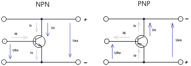
Uke = collector-emitter voltage
Ube = base-emitter voltage
Ic = collector current
Ib = base current
Depending on the states in which the transitions of the transistor are located, the modes of its operation are distinguished. Since the transistor has two transitions (emitter and collector), and each of them can be in two states: 1) open 2) closed. There are four modes of operation of the transistor. The main mode is the active mode, in which the collector junction is in the closed state, and the emitter junction is in the open state. Transistors operating in the active mode are used in amplifying circuits. In addition to the active, there is an inverse mode, in which the emitter junction is closed and the collector junction is open, a saturation mode, in which both junctions are open, and a cut-off mode, in which both junctions are closed.
When the transistor operates with high-frequency signals, the time of the main processes (the time of movement of carriers from the emitter to the collector) becomes commensurate with the period of change of the input signal. As a result, the ability of a transistor to amplify electrical signals deteriorates with increasing frequency.
Some parameters of bipolar transistors
Constant/pulse voltage collector - emitter.
Constant voltage collector - base.
Constant voltage emitter - base.
Base current transfer ratio limit frequency
Direct/pulse collector current.
Current transfer ratio
Maximum allowable current
Input impedance
Dissipated power.
p-n junction temperature.
Ambient temperature, etc…
Boundary voltage Ukeo gr. is the maximum allowable voltage between collector and emitter, with base open circuit and collector current. The voltage on the collector is less than Ukeo gr. characteristic of the pulsed operating modes of the transistor at base currents other than zero and the base currents corresponding to them (for npn transistors base current>0, and for p-n-p vice versa, Ib<0).
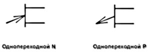
Bipolar transistors can be classified as unijunction transistors, such is, for example, KT117. Such a transistor is a three-electrode semiconductor device with one p-n junction. A unijunction transistor consists of two bases and an emitter.
Recently, composite transistors have often been used in circuits, they are called a pair or Darlington transistors, they have a very high current transfer coefficient, they consist of two or more bipolar transistors, but ready-made transistors are also produced in one package, such is for example TIP140. They turn on with a common collector, if you connect two transistors, they will work as one, the inclusion is shown in the figure below. The use of a load resistor R1 allows you to improve some of the characteristics of the composite transistor.

Some disadvantages of the composite transistor: low performance, especially the transition from open to closed. The forward voltage drop across the base-emitter junction is almost twice that of a conventional transistor. Well, of course, you need more space on the board.
Checking bipolar transistors
Since the transistor consists of two junctions, each of which is a semiconductor diode, you can test the transistor in the same way as you test a diode. The transistor is usually checked with an ohmmeter, both p-n junctions of the transistor are checked: collector - base and emitter - base. To check the direct resistance of the p-n-p transistor junctions, the negative terminal of the ohmmeter is connected to the base, and the positive terminal of the ohmmeter is connected in turn to the collector and emitter. To check the reverse resistance of the transitions, the positive terminal of an ohmmeter is connected to the base. When checking n-p-n transistors, the connection is made the other way around: direct resistance is measured when connected to the base of the positive terminal of the ohmmeter, and reverse resistance is measured when connected to the base of the negative terminal. Transistors can also be called with a digital multimeter in the diode continuity mode. For NPN, we connect the red probe of the device "+" to the base of the transistor, and alternately touch the black probe "-" to the collector and emitter. The device should show some resistance, from about 600 to 1200. Then we change the polarity of connecting the probes, in this case the device should not show anything. For a PNP structure, the order of verification will be reversed.
I want to say a few words about MOSFET transistors (metal-oxide-semiconductor field-effect transistor), (Metal Oxide Semiconductor (MOS)) - these are field-effect transistors, not to be confused with ordinary field-effect transistors! Field-effect transistors have three terminals: G - gate, D - drain, S - source. There are N channel and P, in the designation of these transistors there is a Schottky diode, it passes current from the source to the drain, and limits the drain-to-source voltage.

They are mainly used for switching high currents, they are controlled not by current, like bipolar transistors, but by voltage, and as a rule, they have a very low open channel resistance, the channel resistance is constant and does not depend on current. MOSFET transistors are specially designed for key circuits, it can be said as a relay replacement, but in some cases it can also be amplified, they are used in powerful low-frequency amplifiers.
The advantages of these transistors are as follows:
Minimum drive power and high current gain
Better performance, such as faster switching speed.
Resistant to large voltage impulses.
Circuits using such transistors are usually simpler.
Minuses:
They cost more than bipolar transistors.
Afraid of static electricity.
Most often, N-channel MOSFETs are used for switching power circuits. The control voltage must exceed the threshold of 4V, in general, 10-12V is needed to reliably turn on the MOSFET. The control voltage is the voltage applied between gate and source to turn on the MOSFET.
The values of most transistor parameters depend on the actual operating mode and temperature, and with increasing temperature, the transistor parameters may change. The reference book contains, as a rule, typical (averaged) dependences of transistor parameters on current, voltage, temperature, frequency, etc.
To ensure reliable operation of transistors, it is necessary to take measures that exclude long-term electrical loads close to the maximum permissible ones, for example, it is not worth replacing a transistor with a similar but lower power, this applies not only to power, but also to other parameters of the transistor. In some cases, to increase power, transistors can be connected in parallel, when the emitter is connected to the emitter, the collector to the collector, and the base to the base. Overloads can be caused by various reasons, for example from overvoltage, fast diodes are often used for overvoltage protection.
As for the heating and overheating of transistors, the temperature regime of transistors not only affects the value of the parameters, but also determines the reliability of their operation. You should strive to ensure that the transistor does not overheat during operation; in the output stages of amplifiers, transistors must be placed on large radiators. The protection of transistors from overheating must be ensured not only during operation, but also during soldering. When tinning and soldering, measures should be taken to prevent overheating of the transistor; it is advisable to hold transistors during soldering with tweezers to protect against overheating.
TRANSISTOR SCHEMES
Any amplifier, regardless of frequency, contains from one to several amplification stages. In order to have an idea on the circuitry of transistor amplifiers, let's take a closer look at their circuit diagrams.
Transistor cascades, depending on the options for connecting transistors, are divided into:
1 Common emitter cascade(the diagram shows a stage with a fixed base current - this is one of the varieties of transistor bias).
2 Common collector cascade
3 Common base cascade
![]()
Common emitter cascade has high voltage and current gain. The disadvantages of this switching circuit include the low input impedance of the cascade (of the order of hundreds of ohms), high (of the order of tens of Kilooms) output impedance. A distinctive feature is the change in the phase of the input signal by 180 degrees (that is, inversion). Due to the high gain, the circuit with OE is predominantly used in comparison with OB and OK.
Consider the operation of the cascade in more detail: when an input voltage is applied to the base, the input current flows through the base-emitter junction of the transistor, which causes the transistor to open and, as a result, an increase in the collector current. A current flows in the emitter circuit of a transistor equal to the sum of the base current and the collector current. On the resistor in the collector circuit, when current passes through it, a certain voltage arises, a value much greater than the input. Thus, the voltage amplification of the transistor occurs. Since the current and voltage in the circuit are interrelated quantities, the input current amplifies in a similar way.
Common Collector Circuit has high input and low output impedance. The voltage gain of this circuit is always less than 1. The input impedance of the cascade with OK depends on the load resistance (Rн) and more than it (approximately) in H21e times. (The value "H21e" is the static gain of this instance of the transistor connected according to the Common Emitter circuit). This circuit is used to match stages, or in the case of using an input signal source with a high input impedance. Such a source can be, for example, a piezoelectric pickup or a condenser microphone. The circuit with OK does not change the phase of the input signal. Sometimes this scheme is called emitter follower.
Scheme of switching on a transistor with a common base It is mainly used in cascades of high-frequency amplifiers. The OB stage amplification provides voltage-only amplification. This inclusion of the transistor allows you to more fully use the frequency characteristics of the transistor with a minimum noise level. What is the frequency response of a transistor? This is the ability of a transistor to amplify high frequencies close to the cutoff frequency of the amplification. This value depends on the type of transistor. A higher frequency transistor is capable of amplifying higher frequencies. As the operating frequency increases, the gain of the transistor decreases. If, for example, a circuit with a common emitter is used to build an amplifier, then at a certain (limiting) frequency, the cascade stops amplifying the input signal. The use of the same transistor, but connected according to a common base circuit, allows you to significantly increase the cutoff frequency of the gain. The cascade, assembled according to the scheme with a common base, has low input and low output resistances (these parameters are very well consistent when working in antenna amplifiers using the so-called "coaxial" unbalanced high-frequency cables, the impedance of which, as a rule, does not exceed 100 ohms). If we compare the resistance values for a cascade with OE and OB, then the input resistance of the cascade with OB is (1 + H21e) times less than with OE, and the output resistance is (1 + H21e) times greater. Cascade with OB does not change the phase of the input signal.
In the practice of a radio amateur, it is sometimes necessary to use the parallel connection of transistors to increase the output power (collector current). One of the options for this inclusion is shown below:

With this inclusion, one should strive to use transistors with close parameters Vst. In this case, high power transistors must be installed on one heat sink. To further equalize the currents in this circuit, resistors are used in the emitter circuits. The resistance of the resistors should be selected based on the voltage drop across them (in the operating current range) of about 1 volt (or at least not less than 0.7 volts). This scheme should be used with great care, since even transistors of the same type and from the same production batch have a very large spread in parameters. The failure of one of the transistors will inevitably lead to the failure of other transistors in the chain ... When two transistors are connected in parallel, the maximum total collector current should not exceed 1.6-1.7 of the maximum collector current of one of the transistors! The number of transistors included in this circuit can be as large as desired - it all depends on the expediency ...
In amateur radio practice, sometimes a transistor with a conductivity different from the existing one is required(for example - in the output stage of the ultrasonic frequency converter, etc.). The switching circuit below allows you to get out of the situation:

This cascade usually uses low power transistor VT1 necessary conductivity, transistor VT2 required power but different conductivity. This stage is (in particular) equivalent to a high power N-P-N transistor with a high base current transfer ratio (h21E). If we use transistors of opposite conductivity as VT1, VT2, we will get a powerful composite transistor with P-N-P conductivity.
If transistors of the same structure are used in this circuit, we get the so-called Composite transistor. Such a connection of transistors is called Darlington scheme. The industry produces such transistors in one package. There are both low-power (such as KT3102, etc.) and powerful (for example, KT825) composite transistors.
And now let's talk a little about the temperature stabilization of the amplifier.
The transistor, being a semiconductor device, changes its parameters when the operating temperature changes. So, as the temperature rises, the amplifying properties of the transistor deteriorate. This is due to a number of reasons: as the temperature rises, such a transistor parameter as the collector reverse current increases significantly. An increase in the reverse current of the transistor collector leads to a significant increase in the collector current and to a shift in the operating point in the direction of increasing current. At a certain temperature, the collector current of the transistor increases to such a value at which the transistor stops responding to a weak input (base) current. Simply put, the cascade ceases to be amplifying. In order to extend the operating temperature range, it is necessary to apply additional measures for temperature stabilization of the operating point transistor. The simplest way is collector stabilization of the operating bias current. The cascade circuit we have considered above according to the common emitter circuit is a circuit with a fixed base current. The collector current in this circuit depends on the parameters of a particular instance of the transistor and must be set individually by selecting the value of the resistor R1. When changing the transistor, the initial (in the absence of a signal) collector current has to be selected again, since transistors of even the same type have a very large spread in the static gain of the base current (h21 Oe). Another kind of cascade is the fixed bias circuit. This scheme also has the disadvantages described above:

To increase the thermal stability of the cascade, it is necessary to use special switching circuits:
![]()
The collector stabilization circuit, having the main disadvantages of a circuit with a common emitter (selection of a base bias resistor for a specific instance of the transistor), nevertheless allows you to expand the operating temperature range of the cascade. As you can see, this circuit is distinguished by the connection of the bias resistor not to the power source, but to the collector circuit. Thanks to this inclusion, it was possible to significantly (due to the use of negative feedback) to expand the operating temperature range of the cascade. With an increase in the reverse current of the transistor collector, the collector current increases, which causes a more complete opening of the transistor and a decrease in the collector voltage. Reducing the collector voltage, in turn, reduces the initial bias voltage of the transistor, which causes the collector current to decrease to an acceptable value. Thus, negative feedback is carried out, which somewhat reduces the amplification of the cascade, but it allows you to increase the maximum operating temperature.
Better stabilization of the temperature parameters of the amplification stage can be achieved if the circuit is somewhat more complicated and the so-called "emitter" is applied. temperature stabilization. This circuit, despite its complexity, allows the cascade to maintain amplifying properties in a very wide range of operating temperatures. In addition, the use of this stabilization circuit makes it possible to replace transistors without further tuning. Separately, I will say about the capacitor C3. This capacitor serves to increase the gain of the AC stage. It eliminates the negative feedback of the cascade. The capacitance of this capacitor depends on the operating frequency of the amplifier. For an audio frequency amplifier, the capacitance of the capacitor can vary from 5 to 50 microfarads, for the radio frequency range - from 0.01 to 0.1 microfarads
(but in some cases it may not be).ATTENTION! The calculation data are quite approximate! The final value of the resistor R1 will need to be selected more accurately during commissioning!

First, we need to decide on the initial data for the calculation. The upper rectangle shows constant values for germanium (Ge) and silicon (Si) transistors, respectively.
To start the calculation, we need the following input parameters:Supply voltage(Uk), in Volts (We take - as an example - equal to 6 volts). Collector current (Ik), in Milliamps (we take equal to 1 milliamp); transistor type (Ge. Si), minimum operating frequency Fmin in hertz (assume 150,000 hertz - for operation in the LW range). Collector resistance R3 take equal to 1 kiloohm. The value of this resistor is usually not calculated, but is taken equal to 750 ohms - 4.7 Kilooms. The value of this resistor determines the gain of the cascade for alternating current. Transistor, suppose KT315 - silicon. We carry out the calculation according to the figure from top to bottom!
First, using the formula, we calculate the resistance of the resistor in the emitter circuit R4 \u003d 0.6 kilo-ohm.
Next, we find the resistance of the resistor R2 \u003d 19.5 kilo ohms.
Further - the resistance of the resistor R1 \u003d 70.5 Kiloom.
According to the formula, we calculate the minimum capacitance of the capacitor C1 = 0.016 microfarads. Here, without degrading the frequency properties of the cascade, you can put a capacitor with a larger capacity (for example, by 0.022 microfarads).
So, having made simple calculations, we got a calculated cascade for operation in a radio frequency amplifier. Since during the calculation we received resistor values that do not correspond to the standard series, we can slightly correct them. So instead of the resistor R4, you can put a 620 ohm resistor, replace the R2 resistor with a resistor with a nominal value of 20 kilo-ohms, replace the R1 resistor with a 75 kilo-ohm resistor. These minor deviations from the calculation will not lead to any problems during the operation of the cascade - just a slight change in the collector current ...
Now let's calculate the work of the cascade for alternating current:
For this calculation, we need the following parameters: Resistors R1 - R4, Input resistance of the next (load) stage.

First, we determine the resistance Re. For our case (collector current 1 milliamp) Re = 26 ohm,
Next, we determine the conductivity S = 38.46 microsiemens (approximately),
We calculate the value of R11. For a transistor of the KT315B type, the average value of the h21e parameter is 200, hence R11 is 5200,
The value of Rb must be determined to calculate the input resistance of the stage, which is the load being calculated. It is equal (with the resistor values taken in our example) 5.75 kilo-ohm,
To simplify the calculation, you can not calculate the resistance Rn, but take it equal to R3.
The expected gain of this cascade on a KT315B type transistor with an average value of h21e equal to 200 is about 40.
It should be borne in mind that the obtained value of the cascade gain is very approximate! In practice, this value may differ by 1.5 - 2 times (sometimes more) and depends on the specific instance of the transistor!
When calculating the amplification factor of the transistor stage for alternating current, it should be taken into account that this coefficient depends on the frequency of the amplified signal. The maximum frequency of the applied transistor should be at least 15-20 times higher than the limiting gain frequency (determined from the reference).
To write this page, materials from the book "A Brief Radio Engineering Handbook" were used. Authors Bogdanovich and Vakser, Belarus Publishing House, 1976.
Literature